

In this project, a small disc magnet is levitated by a solenoid that is PID controlled by an FPGA at 156 kHz sample rate. A slower open loop is driven by a Raspberry Pi to stably move the magnet between set points. The Pi communicates the set point, steady state voltage, and gains, thus slowly making big transitions by commanding smaller jumps with accurate linearization. A video of the system in action can be found here.
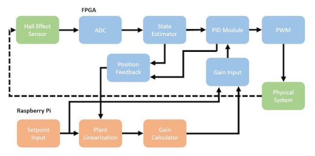
Figure 2 shows a block diagram of the system components. As shown in Figure 1, the physical system is composed of a solenoid above a disc magnet. A PID controller is implemented on an FPGA to control the position of the disc magnet. The 10-bit position of the magnet is measured by the Hall-effect sensor, which is located about an inch below the solenoid so it avoids saturation from the solenoid’s magnetic field but still detects the disc-magnet’s field. The voltage from the sensor is passed through an ADC and then through a pre-calibrated lookup-table to estimate the position of the magnet. The position is then compared to the desired setpoint and used to compute a voltage across the solenoid. The voltage is computed by a PID controller that implements discrete-time derivative filtering for improved performance. This voltage is then passed through a PWM to generate a binary control signal. This control signal leaves the FPGA and is applied to a transistor which controls the current flow to the solenoid.
The linearized gains and feed-forward voltages most applicable to a given setpoint were found in calibration and stored on a Raspberry Pi. The Raspberry Pi takes a desired setpoint and passes the associated gains and feed-forward voltage to the FPGA’s PID module over SPI. In order to create the up-and-down motion seen in the video, the Pi takes small, discrete steps to march the magnet to the endpoints, holding each command for a time long enough for the magnet to reach the desired intermediate location and dissipate its transient response.
The project was done as a joint final project for the Harvey Mudd College courses Microprocessor Design (E155) and Systems Simulation (E205). The project was done in collaboration with Vaibhav Viswanathan.
